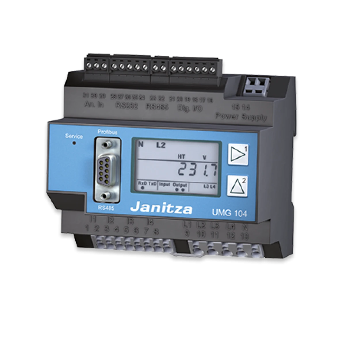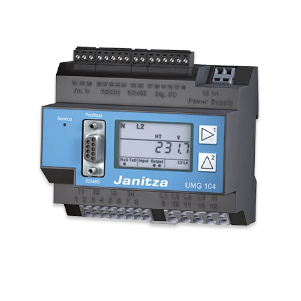
Janitza Power Analyser UMG 104
- Measurement in IT, TN and TT systems,
- 4 voltage measurement inputs
- 4 current measurement inputs,
- Continuous scanning of the voltage and current measurement inputs,
- Energy measurement, measurement uncertainty class 0.5 for ../5A current transformers,
- Energy measurement, measurement uncertainty class 1 for ../1A current transformers,
- Registers more than 800 measured values (readings),
- 2 digital inputs,
- 2 digital outputs,
- Temperature measurement input,
- LC display, backlight (optional),
- Profibus DPV0 (optional),
- RS485 (modbus RTU),
- RS232,
- Suitable for installation in distribution boards,
- Suitable for measurements in networks with frequency inverters.
| Marcă: |

|
| Unitate: | Each |
| Cod: | OTH-JAN-POWERA-104 |
| Garanție: | 2 an |
| General information | |
| Net weight | 350g |
| Device dimensions | approx l=107.5 mm, b=90 mm, h=82 mm (according to DIN 43871:1992) |
| Housing flammability class | UL94V-0 |
| Installed position | any |
| Fixing/mounting | 35 mm top hat rail (according to IEC/EN 60999-1, DIN EN 50022) |
| Battery | Type VARTA CR2032, 3 V, Li-Mn |
| Backlight lifetime (optional) | 40000h (50% of initial brightness) |
| Ambient conditions during operation | |
| The UMG104 is intended for weather-protected, stationary use. The UMG104 fulfils the use conditions according to DIN IEC 60721-3-3. | |
| Operating temperature range | -10°C. +55°C |
| Relative humidity | 5 to 95 %, (at +25 °C) without condensation |
| Degree of pollution | 2 |
| Operating altitude | 0 .. 2000 m above sea level |
| Installed position | any |
| Ventilation | Forced ventilation is not required. |
| Transport and storage | |
| The following information applies to devices which are transported or stored in the original packaging. | |
| Free fall | 1m |
| Temperature | -20°C to +70°C |
| Power supply voltage | |
| The power supply voltage must be connected to the UMG104 via a UL listed fuse. | |
| Line circuit breaker | 6A, Typ C (approved to UL / IEC) |
| Cylindrical fuses | 0.6A, tripping characteristics M (medium time lag) |
| Cylindrical fuses | 0.75A, tripping characteristics F (fast acting) |
| Option 230V: | |
| Nominal range | 95V .. 240V (50/60 Hz) or DC 135V .. 340V |
| Operating range | +-10% of nominal range |
| Installation overvoltage category | 300V CATIII |
| Power consumption | max 3.2W, max 9VA |
| Option 90V | |
| Nominal range | 50V .. 110V (50/60 Hz) or DC 50V .. 155V |
| Operating range | +-10% of nominal range |
| Installation overvoltage category | 300V CATII |
| Power consumption | max 3.2W, max 9VA |
| Option 24V | |
| Nominal range | 20V .. 50V (50/60 Hz) or DC 20V .. 70V |
| Operating range | +-10% of nominal range |
| Installation overvoltage category | 300V CATII |
| Power consumption | max 5W, max 8VA |
| Connectable conductors | |
| Only one conductor may be connected per terminal connection! | |
| Solid core, multi-core, flexible core | 0.08 - 2,5 mm2, AWG 28 - 12 |
| Pin-end connector, wire end ferrules | 1.5 mm2, AWG 16 |
| Protection class | |
| Class II according to IEC 60536 (VDE 0106, Part 1), i.e. a PE terminal is not required! | |
| Protection against ingress of solid foreign bodies and water | IP20 according to EN 60529 September 2000, IEC 60529:1989 |
| Inputs and outputs | |
| 2 digital inputs | |
| Pulse input (S0) | |
| Maximum counting frequency | 20 Hz |
| Switching input | |
| Response time (Jasic program) | 200 ms |
| Input signal applied | 18V. 28 V DC (typically 4 mA) |
| Input signal not applied | 0 .. 5 V DC, current less than 0.5 mA |
| 2 digital outputs, semi-conductor relay, not short-circuit proof. | |
| Switching voltage | max 60 V DC, 30 V AC |
| Switching current | max 50 mAeff AC/DC |
| Response time (Jasic program) | 200 ms |
| Output of voltage dips | 20 ms |
| Output of voltage overranges | 20 ms |
| Pulse output (operating pulses) | max 20 Hz |
| Cable length | up to 30 m greater than 30m shielded |
| Connectable conductors | |
| Solid core, multi-core, flexible core | 0.08 - 1.5 mm2 |
| Pin-end connector, wire end ferrules | 1 mm2, only one conductor may connected per terminal connection! |
| Temperature measurement input | |
| Update time | approx 200 ms |
| Connectable sensors | PT100, PT1000, KTY83, KTY84 |
| Total burden (sensor + cable) | max 4 kohm |
| Sensor type | Temperature range | Resistance range | Measurement uncertainty |
| KTY83 | -55 ° .. +175 °C | 500 ohm .. 2.6 kohm | ± 1.5% rng |
| KTY84 | -40 ° .. +300 °C | 350 ohm .. 2.6 kohm | ± 1.5% rng |
| PT100 | 99 ° .. +500 °C | 60 ohm .. 180 ohm | ± 1.5% rng |
| PT1000 | -99 ° .. +500 °C | 600 ohm .. 1,8 kohm | ± 1.5% rng |
| Cable length | up to 30 m unshielded, greater than 30 m shielded |
| Connectable conductors: | |
| Solid core, multi-core, flexible core | 0.08 - 1.5 mm2 |
| Pin-end connector, wire end ferrules | 1 mm2, only one conductor may be connected per terminal connection! |
| Interfaces | |
| RS232 | 5 pin screw-type terminals |
| Protocol | Modbus RTU/slave |
| Transfer rate | 9600 bps, 19.2 kbps, 38.4 kbps, 115.2 kbps |
| RS485 | 2 pin screw-type terminals |
| Protocol, modbus RTU | Modbus RTU/slave |
| Transfer rate | 9.6 kbps, 19.2 kbps, 38.4 kbps, 57.6 kbps, 115.2 kbps, 921.6 kbps |
| RS485 (optional) | Connector, SUB D 9 pin |
| Protocol, profibus (optional) | Profibus DP/V0 according to EN 50170 |
| Transfer rate | EN 50170 Transfer rate : 9.6 kbaud up to 12 Mbaud |
The UMG104 is intended to be used for the measurement and calculation of electrical variables such as voltage, current, energy, work, harmonic components, etc. in building installations, at distribution boards, circuitbreakers and busbar trunking systems. Measuring-circuit voltages and currents must originate from the same system. The UMG104 is permanently installed in control cabinets or small distribution boards. It can be installed in any position. The measurement results can be displayed, stored and read out via serial interfaces and further processed. The voltage measurement inputs are designed for measurements in low-voltage systems in which rated voltages up to 300 V conductor to earth and surge voltages of overvoltage category III can occur. The current measurement inputs of the UMG104 are connected via external ../1A or ../5A current transformers. Mains failure detection The mains failure detection takes place via the voltage measurement inputs. The selection of voltage measurement inputs can be configured using the GridVis software. Mains failure stored energy time The UMG104 bridges the following mains failures at the auxiliary voltage input: Mains voltage Stored energy time 230V AC max 80ms

