Power Analyse JANITZA UMG 103
- Harmonics
- Modbus interface
- GridVis Analysis software
| Marcă: |

|
| Unitate: | pcs |
| Cod: | OTH-JAN-POWERA-103 |
| Garanție: | 2 an |
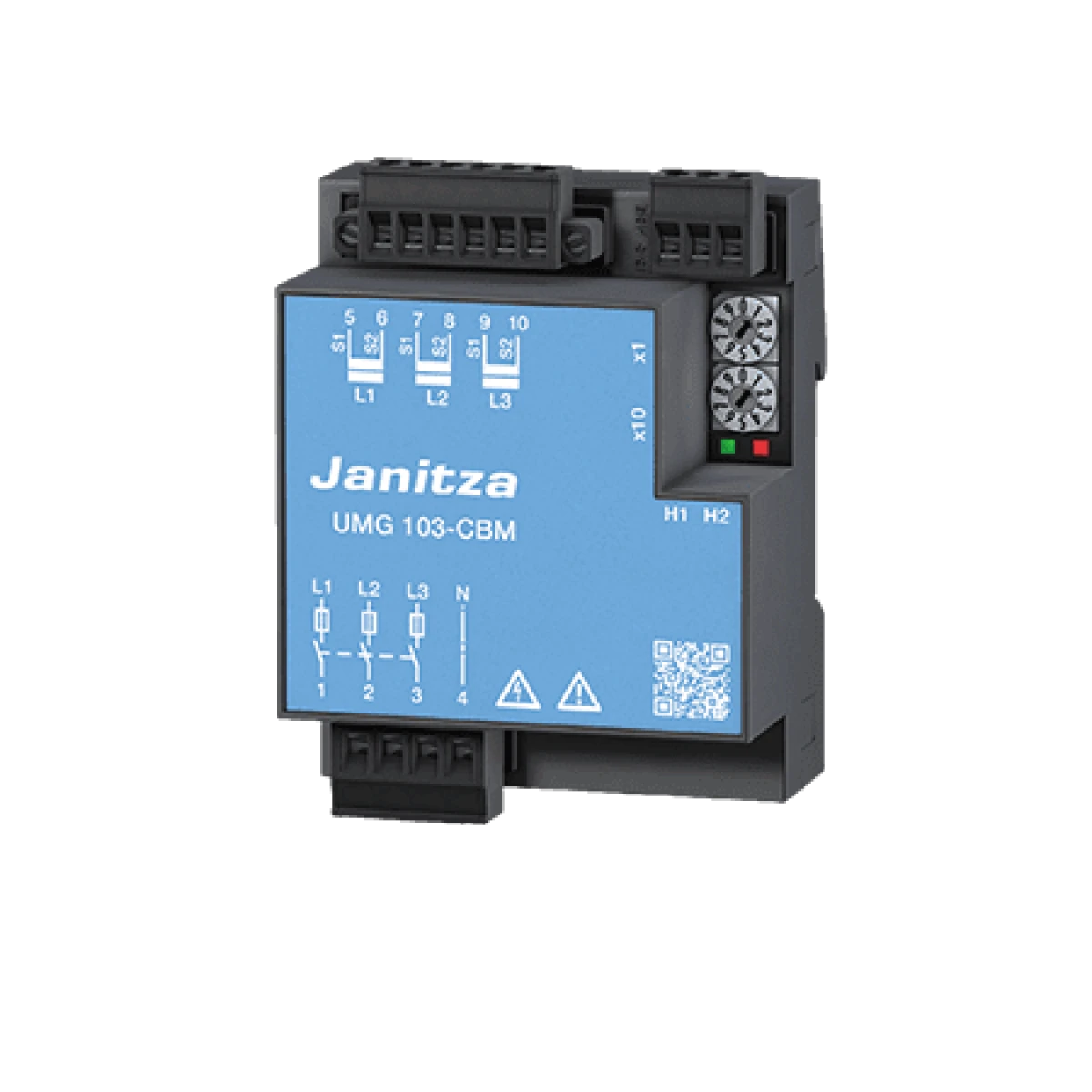
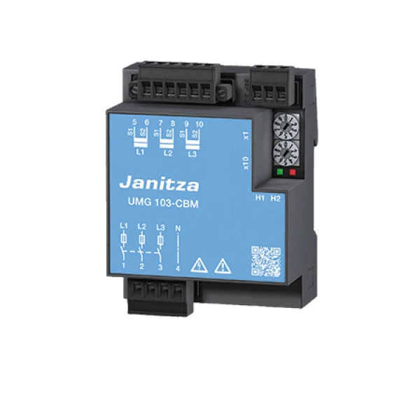
The UMG103 is intended to be used for the measurement and calculation of electrical variables such as voltage, current, power, work, harmonic components, etc. in building installations, at distribution boards, circuit-breakers and busbar trunking systems.
It can be installed in any position. The measurement results can be read out via the RS485 interface. The UMG103 draws its power supply voltage from the measuring-circuit voltage. The UMG103 is designed for operation in low-voltage distribution systems, in which overvoltage category III (300 V) impulse voltages can occur. The UMG103 can measure L-N voltages of up to 240 V and short-term overvoltages up to 300 Vrms.
| General Data | |
| Net weight (with attached connectors) | approx. 200 g |
| Device dimensions | H = 98 mm, W = 71.5 mm, D = 46 mm |
| Ambient conditions during operation | |
|
The device
|
|
| Working temperature range | K55 (–10°C to +55°C) |
| Relative humidity | 5 to 95% (at +25° C) without condensation |
| Operating altitude | 0 to 2000 m above sea level |
| Pollution degree | 2 |
| Housing flammability rating | UL94V-0 |
| Installation position | any |
| Ventilation | No forced ventilation required. |
| Fastening/assembly | DIN rail 35 mm as per IEC/EN60999-1, DIN EN50022 |
| Impact stress | 2 Joule, IK07 as per IEC/EN61010-1:2010 |
| Protection against ingress of solid foreign bodies and water | IP20 in accordance with EN60529, September 2000, IEC60529:1989 |
| Measurement data recording | |
| Recording period | Up to 144 days |
| Memory (Flash) | 4 MB, (1024 sectors. each 4kB) |
| Data record storage (all profiles activated) | approx. 16000 data records |
| Battery (soldered in) , typical life expectancy | BR 1632, 3V, 8 - 10 years |
| Transport and storage | |
| Free fail | 1 m |
| Temperature | K55 (–20° C to +70° C) |
| Relative humidity | 0 to 90% RH |
| Supply voltage | |
| The device derives the supply voltage from the measured voltage! | |
| Supply from single phase | 115 - 277 V (±10%), 50/60 Hz |
| Supply from three phases | 80 - 277 V (±10%), 50/60 Hz |
| Power consumption | max. 1.5 VA |
| Voltage measurement | |
| 3-phase 4-conductor systems with rated voltages (L-N/L-L) | Max. 277 V/480 V |
| Networks | Measurement in TT and TN networks |
| Measurement voltage surge | 4 kW |
| Protection of voltage measurement | 1 - 10 A trigger characteristic B, (with IEC-/UL approval) |
| Overvoltage category | 300 V CAT III |
| Resolution | 0.01 V |
| Crest factor | 2 (based on 240 Vrms) |
| Sampling rate | 5.4 kHz |
| Frequency of the fundamental oscillation resolution |
45 Hz to 65 Hz 0.001 Hz |
| Fourier analysis | 1.-25. harmonics (all odd) |
| Current measurement | |
| Rated current | 5 A |
| Rated current | 6 A |
| Crest factor | 2 (based on 6 Arms) |
| Resolution | 0.1 mA |
| Metering range | 0.005 to 6 Arms |
| Overvoltage category | 300 V CAT II |
| Measurement voltage surge | 2 kV |
| Power consumption | approx. 0.2 VA (Ri=5 mΩ) |
| Overload for 1 sec. | 60 A (sinusoidal) |
| Sampling rate | 5.4 kHz / phase |
| Terminal connection capacity | |
| Connectable conductors. Connect only one conductor per terminal! | |
| Single core, multi-core, fine-stranded | 0.08 - 2.5 mm2, AWG 28 - 12 |
| Tightening torque | max. 0.5 Nm |
| Stripping length | min. 8 mm |
| RS485 interface | |
| Protocol, Modbus RTU | Modbus RTU/slave |
| Transmission rate | 9.6 kbps, 19.2 kbps, 38.4 kbps, 57.6 kbps, 115.2 kbps, automatic detection |
| Firmware | |
| Firmware update |
Update via GridVis®software. Firmware download (free of charge) from the website: http://www.janitza.com |

