Battery Energy Storage: From Batteries to Energy Management
If you're designing an energy storage system, it's important to understand the entire chain, not just the capacity. Battery-based energy storage is a coordinated system in which the battery is just one component. First, we’ll look at how the process works and why a battery alone isn’t enough. Then we’ll discuss the basics of solar energy storage, including the battery and the monitoring electronics that protect it.
We’ll cover how the inverter or PCS converts direct current to alternating current and back again. We’ll show you what the smart meter measures at the grid connection point. The EMS is the controller that determines when and how much the system should charge or discharge. We’ll also look at the communication protocols (RS485, Modbus, CAN, Ethernet) used by the devices to communicate with each other.
Next, we’ll cover the interaction between the solar panels and the storage system, typical operating modes, and how the EMS works in practice. We’ll show you when the control system goes beyond simply increasing self-consumption, and how a residential system differs from an industrial one. Finally, you’ll find selection criteria and SOLARKIT’s expert opinion.
How does battery energy storage work?
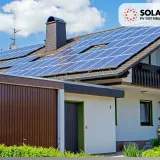
If you’re wondering how battery energy storage works, the simplest way is to follow the path of energy from the roof to the outlet. Solar panels generate direct current (DC), which the inverter converts into alternating current (AC) suitable for household use. The energy generated is first used by the home’s own consumers. If generation exceeds current consumption, the surplus is not fed into the grid but is used to charge the battery. Once the battery is full, the system feeds any further surplus into the grid, provided this is permitted.
In the evening, on cloudy days, or during a power outage (if the system is capable of off-grid operation), the process reverses. The battery discharges, and the inverter converts the stored direct current back into alternating current. The system performs this conversion automatically, without human intervention. If the stored energy runs out and the solar panels are not generating power, the grid takes over the supply.
The essence of solar battery storage is therefore time shifting: you use the surplus generated during the day when the solar panels are no longer producing energy. This is significant because many households consume the most energy in the morning and early evening, when the solar panels provide very little electricity. It’s important to clarify: the battery itself does not generate energy; it only stores and releases it.
Why isn’t a battery alone enough?
An energy storage battery, on its own, only stores energy in chemical form. It cannot determine when to charge, when to discharge, or how much current to deliver, nor can it convert direct current (DC) into a form usable by the household—an inverter or PCS is required for this.
Furthermore, lithium-ion cells are sensitive. Overcharging, deep discharge, excessive current, or operation outside the permissible temperature range can lead to thermal runaway, which can even cause a fire. The BMS system is designed to prevent this; it continuously monitors the state of charge and state of health, and in the event of a hazard, it disconnects the battery or reduces the charging and discharging current. It manages voltage differences between cells through balancing, because without this, the weakest cell would limit the capacity of the entire battery pack. These risks are partly related to cell chemistry as well. The energy storage systems we distribute are therefore built with lithium iron phosphate (LFP, LiFePO₄) cells, which have better thermal stability than NMC cells with higher energy density. This will be discussed in detail in the next chapter.
However, no matter how safe the cell is, the system must also be able to monitor what is happening inside the building and at the grid connection point. This requires measurement capabilities, and making decisions requires higher-level control—a BMS. You can read about these in detail in the following chapters.
The foundation of a solar energy storage system: the battery
The battery is the heart of every solar energy storage system, so the system’s capabilities are largely determined by the cell chemistry on which it is based. For residential storage systems, lithium iron phosphate (LFP, LiFePO4) is one of the most common choices today. Compared to NMC (nickel-manganese-cobalt) cells, it has a more stable crystal structure and is less prone to releasing oxygen at high temperatures, resulting in greater thermal stability. The advantage of NMC is its higher energy density, which is important where space or weight is a limiting factor.
Another important characteristic is cycle life: this indicates the number of full charge-discharge cycles after which capacity drops to 70 percent of its original value. Based on manufacturer and industry data, an LFP cell typically lasts for 6,000–8,000 cycles, and can even reach 10,000 cycles, while NMC cells generally have a lower cycle life. Assuming one cycle per day, this could mean more than a decade of operation; however, actual service life is also influenced by the depth of discharge (DoD) and temperature. It is important to pay attention to the usable capacity listed on the data sheet, as it may be lower than the nominal capacity: manufacturers typically allow for a depth of discharge of 80–95 percent.
The voltage level of the energy storage battery is also a key factor. There are two main categories in the residential market: low-voltage systems, typically with a nominal voltage of 51.2 V, and high-voltage storage systems, which can reach up to 800 V. Low-voltage versions can be expanded through parallel connection and offer high capacity at an affordable price, while high-voltage systems are better suited for high-energy and high-power applications. The voltage ranges of the battery and the inverter must match; it’s always a good idea to check this before making a purchase.
Battery and Inverter Communication—How Is Energy Converted?
The battery stores direct current (DC), while the household and the utility grid operate on alternating current (AC), so a converter unit is always required between the two. This is the path of the energy. Equally important, however, is the path of information: without communication between the battery and the inverter, the inverter would not know how much current it can draw from or supply to the battery. In lithium-ion systems, therefore, a communication cable connects the two devices, through which the BMS transmits the state of charge and the permitted charge and discharge limits. If this connection is flawless, the two devices operate as a single, coordinated unit.
Battery System Operation and Continuous Monitoring
The operation of the battery system is based on closed-loop communication. In this setup, the BMS and the inverter are in a bidirectional connection, and the BMS continuously sends the state of charge (SOC), voltage, temperature, and the permissible charge and discharge currents to the inverter. If the battery is nearing full charge, the BMS can reduce the charging current to prevent overcharging and allow time for cell balancing. If the temperature exceeds the safe range, charging or discharging slows down or stops entirely if necessary.
In contrast, in an open-loop system, the inverter operates based on preset parameters and does not adjust in real time to the battery’s state. This can lead to less efficient charging, overcharging, or deep discharge, and ultimately result in a shorter service life. According to manufacturers’ experience, closed-loop control can not only extend service life but also reduce recharge time.
Battery monitoring is the visible aspect of this relationship. In a closed-loop system, the state of charge is derived from BMS measurements rather than an estimate based on voltage. Data from the BMS is displayed on the inverter’s screen or on the manufacturer’s cloud platform, allowing you to monitor the state of charge and battery health remotely.
What is the difference between a hybrid inverter and a PCS?
A hybrid inverter combines the functions of a solar inverter and a battery inverter in a single device: it receives direct current from the solar panels via its MPPT inputs, charges and discharges the battery, and then supplies alternating current to the household or the grid. This is a common solution for residential systems, especially in new installations, because a single device manages both the solar panels and the storage system.
The PCS (Power Conversion System) is a bidirectional converter for commercial and industrial storage systems that converts energy between the battery and the grid or consumers, in sync with the grid. Functionally, however, an inverter also contains a PCS: it is actually a combination of a converter (PCS), one or more MPPT units, and, in many cases, a transfer switch (STS) module. Inverters therefore also perform grid compliance, frequency and voltage regulation, and protection functions. The difference lies more in scale and architecture: PCS units are often modular, allowing multiple units to be connected to achieve the desired power output, while charging and discharging are controlled by a separate EMS; on an industrial scale, they may also offer additional functions.
The distinction is therefore not clear-cut: there are PCS units equipped with MPPT inputs, and hybrid inverters are also bidirectional converters. The two terms are often used interchangeably in the industry, so it’s worth comparing the specific functions listed on the data sheet. To put it simply: a hybrid inverter is typically used in a single-family home, while standalone PCS and EMS units are used in industrial-scale systems.
Smart meter: what happens on the grid?
The battery and the inverter, on their own, can only see their own circuit. For the system to make the right decision, it needs to know how much current is flowing in from the grid and how much is flowing back into it. This task is performed by the smart meter—a meter installed at the grid connection point and connected to the inverter, which often uses a current transformer (CT). This is not the same as the utility’s billing meter. The energy management system bases its decisions on the data from this device. Without measurements, the control system would be operating blindly.
What does a smart meter measure?
The smart meter performs bidirectional measurement: it separately records the energy drawn from the grid and the energy fed back into the grid. It also measures instantaneous values, such as voltage, current, power, frequency, and power factor, and typically sends these to the inverter via an RS-485 line using the Modbus-RTU protocol.
Data transmission is fast: in some manufacturer solutions, the meter transmits an averaged power value to the EMS every second, and the EMS in turn sends a new reference signal to the inverter. This allows the system to respond within one second if, for example, the feed-in reaches the permitted limit. This forms the basis for feed-in limitation (export limitation) and zero-feed-in operation, which are required by grid regulations in some areas.
The meter’s location is just as important. It must be placed between the grid and all household consumers and other generators, because only then can it monitor the home’s total energy flow. The difference between instantaneous consumption and generation indicates whether you are currently drawing power or feeding it back into the grid. If the meter is installed in the wrong place—for example, on the consumer side—the system will operate based on incorrect data.
Why is the correct measurement direction important?
The current transformer (CT) is direction-sensitive: the arrow on it indicates which direction of current is considered positive. If it is installed the wrong way around, the system will interpret consumption as feed-in and feed-in as consumption. In this case, the energy storage controller does the exact opposite of what it’s supposed to: it feeds the solar surplus into the grid instead of charging the battery, or it fails to discharge the battery in the evening while the house is drawing power from the grid. In a system set to zero feed-in, the error can also mean that even though the limitation appears to be active, the system is actually feeding back power without restriction.
The correct direction may vary by manufacturer: in some cases, the arrow must point toward the grid, while in other solutions, it must point toward the inverter. Therefore, always refer to the specific installation manual. Some inverters can reverse the measurement direction via software, and some manufacturer apps help filter out errors with a CT verification function.
EMS – the “brain” of the energy storage system
If the BMS is the battery’s guardian, then the EMS (Energy Management System) is the brain of the entire storage system. This higher-level controller decides when, why, and how much energy the system should store or discharge. The EMS communicates directly with the inverter and the BMS, takes into account data from the grid, the solar panels, and the loads, and then uses this information to formulate an operating strategy. In residential systems, it is often integrated into the storage system’s or inverter’s software, but standalone energy management devices also exist. The end result is the same: a central hub that provides a unified view of the entire system.
The Meaning of EMS and BMS
In short, EMS stands for Energy Management System, and BMS stands for Battery Management System. The two acronyms are similar, but their functions operate at different levels.
The BMS operates at the battery level. It monitors the voltage, current, and temperature of the cells, estimates the state of charge and state of health, balances the cells, and performs protective functions. In larger battery packs, it can be multi-level: the individual BMSes of the modules report to a master BMS.
The EMS, on the other hand, operates at the system level. It does not deal with individual cells, but rather with how energy should be distributed among the battery, solar panels, the grid, and consumers, taking grid constraints into account—for example, to increase self-consumption, shift loads, or reduce peak demand.
The two work together: the EMS’s decisions are constrained by the BMS’s limits. If the BMS determines that the battery is too cold or already full, the EMS’s request to charge will be ignored—safety takes priority. In a well-integrated system, this division of labor is seamless: the EMS plans, and the BMS monitors.
What data does the EMS system use?
The EMS system is only as good as the accuracy of the data it uses. Its most important data sources can be divided into four groups.
The first is real-time measurement: grid data from the smart meter, production values from the inverter, and charge levels and thresholds from the BMS. The second is forecasting: advanced systems estimate expected solar panel production based on the installation location and meteorological data, up to 48 hours in advance. The third is consumption patterns: the EMS learns the household’s recurring habits based on previous measurements; some manufacturers require at least a two-week load profile for this. The fourth is the tariff: the feed-in tariff, the electricity price, and—in the case of dynamic tariffs—the price that varies by time period.
The operation of the energy management system is essentially a continuous planning cycle: based on the data, a schedule is created specifying when to charge, when to discharge, and how much reserve to leave. The battery carries this out, the BMS reports the current charge level, and the EMS replans based on this information.
This is why the battery may not charge immediately, even in sunlight. This is intentional: based on the forecast, it will fill up later anyway; this way, the system avoids having to curtail solar panel output due to feed-in restrictions and also extends the battery’s calendar lifespan.
How do the components of the energy storage control system communicate with each other?
As seen in the previous chapters, several independent devices work together in a storage system: the battery, inverter, meter, and EMS. The energy storage control system can only operate reliably if these devices speak a common language. In practice, several proven communication solutions have become widespread: the RS-485 serial bus using the Modbus protocol, the CAN bus, as well as Ethernet and internet connections. Each has its own role, and multiple solutions often run simultaneously within a single system. Below, we provide a brief, practical overview of each.
RS485 and Modbus
RS485 is a physical standard: it defines how signals travel over a twisted-pair cable. Modbus, on the other hand, is the protocol that defines the format in which devices send and receive requests and responses. The serial Modbus network operates on a master–slave principle: a central device sends requests, and the other devices respond only when addressed; they do not communicate with one another.
Multiple devices can be daisy-chained on a single RS485 bus, and at low data rates, it can support cable lengths of up to 1,200 meters. A common application for energy storage systems is connecting smart meters, but many manufacturers also offer RS485 connectivity for communication between batteries and inverters.
Several details must be considered during installation: the correct assignment of pins A and B, bus termination, the data rate, and the Modbus addresses of the devices. If any of these are incorrect, communication may be intermittent or fail entirely.
CAN Communication
The CAN (Controller Area Network) bus was originally developed by Bosch for the automotive industry, but today it is also widely used in industrial automation and battery storage systems. Unlike RS-485 Modbus, there is no mandatory central device here: CAN is a multi-master, broadcast-based system where every node can transmit when the bus is free, and collisions are resolved through bit-by-bit priority arbitration. Differential signal transmission effectively filters out electrical noise, and error detection is part of the protocol.
In residential storage systems, data exchange between the BMS and the inverter often takes place over CAN using an RJ45 cable. Battery modules connected in parallel can also communicate with each other over the same bus. The cable resembles a network cable on the outside, but the pinout may vary by manufacturer; therefore, you must always use the pinout specified by the manufacturer.
Ethernet and Cloud Connectivity
The third layer is the network connection. Many inverters connect to the local network and the internet via a LAN port, Wi-Fi, or a separate data acquisition module (dongle). On some models, Modbus TCP is also available via the Ethernet port, allowing an external EMS or smart home control program to directly read metering, generation, and battery data.
The cloud connection feeds the manufacturer’s monitoring platform: from there, you can access the system’s data on your mobile device, and the installer can remotely diagnose, configure, and even perform firmware updates. Optimization based on dynamic rates and weather forecasts also requires an internet connection.
It’s important to note that local regulations—specifically, restrictions on charging, discharging, and net metering—typically function even without an internet connection. If the connection is lost, the system continues to operate; however, data will not be uploaded to the cloud until the connection is restored.
What happens in the event of a communication error?
The consequences of communication errors depend on which connection is lost.
If the connection between the BMS and the inverter is lost, the inverter cannot determine the battery’s status; therefore, for safety reasons, it limits or stops charging and discharging and displays an error code, such as “BMS Lost” or “BMS communication fault.” In such cases, the battery is usually intact; the cause of the error is often a loose or damaged communication cable. It is also possible that the BMS itself shuts down for safety reasons—for example, due to overcurrent or overheating—which is also reported to the inverter as a communication error.
If the connection to the smart meter is lost, a well-designed system switches to a safe state: it limits the power output to the set feed-in limit.
The battery system is therefore designed so that, in the event of a data loss, safety takes precedence over yield.
Why is battery monitoring important?
Battery monitoring is not merely a convenience feature. There are three reasons why it’s worth checking the data regularly.
The first is early fault detection. BMS alerts indicate when, for example, the cells become unbalanced, the temperature exceeds the safe range, or an overcurrent occurs. These should not be ignored, as they can lead to battery damage or safety risks.
The second is monitoring aging. The State of Health (SOH) indicator shows how capacity changes over the years, allowing you to detect in a timely manner if degradation is occurring faster than expected.
The third is warranty and service. Some installers tie the performance warranty to the system’s online availability, and remote access enables faster troubleshooting.
In the event of an error code, it’s best to leave any intervention—especially firmware updates—to the installer.
How do solar panels and energy storage batteries work together?
The key issue in the interaction between the solar panel and the battery is where the two circuits connect. This determines efficiency, scalability, and the types of components required for the system. There are two basic configurations.
In a DC-coupled system, the solar panels and the battery are connected to the same hybrid inverter, on its common DC side. The DC current from the solar panels directly charges the battery and is converted to AC current only when supplied to loads or the grid. It is also capable of storing the clipped energy from an oversized solar array. When charging from solar panels, it typically achieves a cycle efficiency of 95–98 percent, making it the sensible choice for new installations.
In an AC-coupled system, the solar panels feed into their own inverter, while the battery is connected to the AC side via a separate battery inverter. The stored energy is thus converted up to three times, so the efficiency is typically 90–94 percent. In return, the existing solar panel system remains untouched, making this the obvious choice for retrofitting. The two inverters operate independently of each other, so if one fails, the other can continue to operate.
However, the difference applies only to stored energy: the energy that flows directly from the solar panels to the consumers undergoes a single conversion in both cases. When charging from the grid, the efficiency advantage of DC coupling is lost. Therefore, when designing a solar-battery storage system, what matters is how much energy actually passes through the battery.
If you’re considering which configuration is best for your system, we explore the dilemma of AC-connected versus DC-connected energy storage in detail—including decision-making criteria—in our article.
What operating modes are available in a modern system?
In a state-of-the-art system, energy storage control does not operate according to a single, fixed logic. Manufacturers offer multiple operating modes, from which you can choose based on local rates and user needs. The names vary by manufacturer, but the underlying logic is similar.
Self-use optimization: The priority order is consumers, battery, grid. The solar panel first supplies the home; any surplus charges the battery; and only what remains after that is fed into the grid. This is advantageous where the feed-in tariff is low and the purchase price is high.
Feed-in Priority (Feed-in First): After supplying the home, the surplus solar power is fed primarily into the grid, not into the battery. This makes sense if the feed-in tariff is higher than the price of purchased electricity.
Backup mode: The system maintains the battery at a higher charge level to ensure that critical loads are supplied in the event of a power outage (for systems with a backup output). This is recommended in areas where grid outages are frequent.
Scheduled Charging and Discharging (Force Time Use, Time of Use): The user can specify when the system should charge from the grid and when it should discharge the battery. With a rate plan that applies different prices depending on the time of day, energy stored during cheaper periods can be used during more expensive hours.
Some systems also offer additional modes, such as peak shaving or generator operation. In self-consumption and reserve modes, it is typically possible to set a minimum state of charge (Min SOC) below which the battery will not discharge.
Selecting the appropriate mode is therefore primarily a matter of electricity rates: the same hardware can yield very different savings with different settings.
How the EMS System Works in Practice
To make this more tangible, let’s walk through a day at an imaginary family home equipped with solar panels, a battery, a heat pump, and an electric vehicle charger. This example is for illustrative purposes only; actual behavior varies by manufacturer and settings.
The previous evening, the EMS system sees from the forecast that sunny weather is expected the next day. Therefore, it does not charge the battery from the grid overnight, and in the morning, it discharges the battery to the minimum charge level to cover morning consumption until the solar panels start generating power.
By mid-morning, power generation already exceeds the home’s demand. At this point, the EMS can switch the heat pump to boost mode via the SG Ready connector, so the excess energy is stored as heat in the hot water or buffer tank. If there is no heat pump, a heating element, for example, can be controlled via a relay circuit.
At noon, during peak production, the battery charges, and the electric car also charges using solar energy. Some energy management systems prioritize charging the car with the surplus, and a minimum charge level can be set to ensure there is always sufficient range. The system distributes the surplus in such a way that solar panel production does not need to be curtailed due to the feed-in limit.
In the evening, the battery takes over powering the home. The EMS does not allow the charge level to drop below the set minimum, ensuring a reserve remains overnight, while the BMS continuously monitors the cells.
The operation of the energy management system is therefore a combination of priority order and forecasting: the goal is to utilize as much self-generated energy as possible, at the most favorable time and with the least amount of loss.
When does an energy management system go beyond simple self-consumption?
Increasing self-consumption is the basic task, but an advanced energy management system is capable of much more. In this case, the question is no longer just where self-generated power is used, but also when, at what price, and under what grid conditions.
With dynamic pricing, the EMS charges the battery when electricity is cheap—based on price forecasts—and uses it when it is expensive. This is called energy arbitrage. To do this, it must simultaneously take into account expected generation, consumption, and the battery’s state.
In peak shaving, the goal is to reduce power demand peaks drawn from the grid. Where pricing is tied to the highest power draw, the battery discharges during peak hours, thereby reducing the power charge. This is particularly important where the power charge accounts for a significant portion of the bill.
Compliance with grid regulations is also part of energy management: the system maintains the feed-in limit, and in some markets, it can limit consumption or feed-in at the grid operator’s request.
The highest level is the virtual power plant (VPP). In this case, a central software platform coordinates many geographically dispersed storage units so that they behave as a single, controllable power plant. These systems can participate in both frequency regulation and demand-side response, and the owners receive a portion of the revenue.
Which of these options is available depends on the local market and regulatory environment. When selecting an energy management system, it is therefore worth considering future possibilities as well.
What is the difference between residential and industrial solar battery storage?
The basic principle is the same in both cases: a battery, a BMS, an inverter, and a control system. The difference lies in the scale, the design, and the objectives.
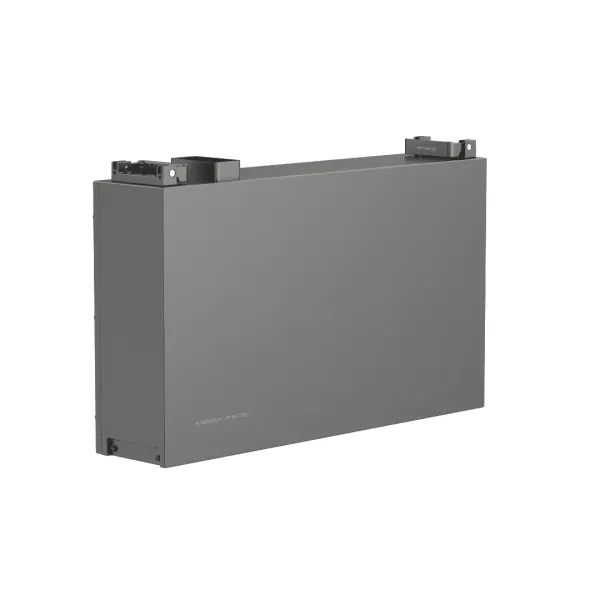
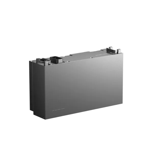
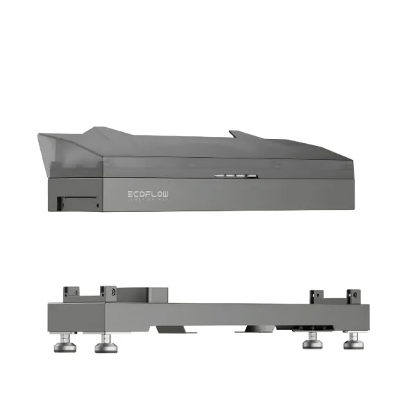
For residential systems, capacity typically ranges from a few kWh to several tens of kWh; a useful capacity of 5–10 kWh is often sufficient to cover average evening and nighttime consumption. Conversion is usually handled by a single inverter, and control is integrated into the inverter’s or storage system’s software. The main goal is to increase self-consumption and provide backup power when needed. Modular, outdoor-ready, and heated models are also available; you can find such solutions, for example, among EcoFlow energy storage systems.
On an industrial and commercial scale, capacity can range from several hundred kWh to megawatt-hours. The systems are available in cabinet or container configurations; the modules’ BMSs are organized into a multi-level hierarchy, conversion is performed by modular PCS units, and control is handled by a separate EMS or SCADA system. All-in-one designs are also common, where the converter, battery, and thermal management system are housed in a pre-integrated cabinet. Thermal management plays a key role; in addition to air cooling, liquid cooling is becoming increasingly widespread, and fire protection and smoke detection systems are also integral parts of the equipment.
The objectives are different as well. At an industrial site, in addition to self-consumption, peak load shaving, load shifting, and grid services play important roles; therefore, sizing is based on the site’s load profile. Safety and power quality requirements are also stricter for grid connection.
Solar-battery storage is thus based on the same fundamental elements; however, on an industrial scale, design, safety, and the business model carry much greater weight.
What factors should you consider when choosing an energy storage system?
Based on what we’ve covered so far, it’s already clear what an energy storage system consists of: a battery with a BMS, an inverter, a meter, and an EMS. When making a choice, therefore, it’s not enough to focus on a single figure, such as kWh. It’s worth considering three groups of factors together: capacity and power, compatibility between components, and control capabilities. Before making a decision, it’s a good idea to gather your own consumption data, because without it, sizing is just an estimate.
Capacity and Power
Capacity (kWh) indicates how much energy the battery can store, while power (kW) indicates how much load it can handle at any given time. The two are not the same: a system with high capacity but low power can last a long time, but it may not be sufficient when a high-power appliance is turned on.
Capacity is primarily determined by evening and nighttime consumption, not by total daily consumption. Always calculate based on the usable capacity, not the rated capacity. When considering power output, it’s worth examining both the continuous power and the short-term peak power, as well as whether the system is limited by the inverter or the energy storage battery. If backup power is also a goal, you’ll need to carefully consider which loads must remain operational during a power outage.
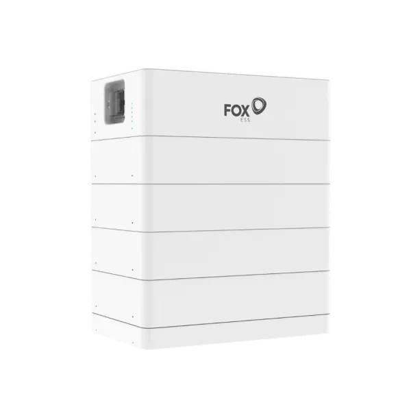
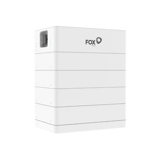
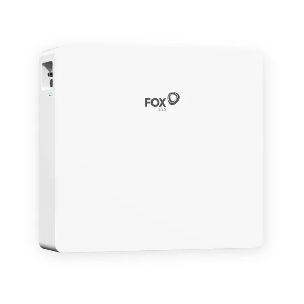
Scalability is also important. With a modular system, capacity can be increased later by adding new modules; you’ll find this type of solution, for example, among FoxEss energy storage systems. However, the conditions for expansion are always determined by the manufacturer’s specifications.
C-Rate and Compatibility
The C-rate indicates how quickly a battery can be charged or discharged relative to its capacity. At 1C, it can be fully charged or discharged in one hour; at 0.5C, in two hours. In practice, this determines the power output: a 10 kWh battery capable of a 0.5C load can sustainably deliver approximately 5 kW. LFP cells typically handle a sustained 0.5C load and a short-term 1C load well. The charge and discharge C-rates may differ; this is specified separately in the data sheet.
Compatibility is just as important. The battery’s voltage range must match that of the inverter, and the communication protocols (CAN or RS485) between the battery and the inverter must also be compatible. High-voltage and low-voltage batteries are not interchangeable, even if they have the same kWh rating. Always check the manufacturer’s current, approved compatibility list at the model and firmware levels. An unapproved pairing may work, but it can lead to error messages, limited performance, or warranty issues.
EMS System Features
The capabilities of the EMS determine how much you can get out of the hardware. It’s worth checking whether the control system supports forecast-based charging and dynamic tariffs, can manage the feed-in limit, and has a peak load shedding function. If you also have a heat pump or an electric vehicle charger at home, it’s important that the EMS can control these as well, for example, via an SG Ready or EEBUS connection.
An open interface, such as Modbus TCP, allows you to connect to external systems later on. Also check out the manufacturer’s app, see if remote updates are available, and find out what cybersecurity protections the manufacturer offers. This is important because you’re typically purchasing a storage system for decades of operation, and the software may be enhanced with updates over that time. Finally, make sure that the local controls work even without an internet connection.
SOLARKIT’s Take on Battery Energy Storage
As a solar panel wholesaler and a partner providing technical support, we’ve observed that the success of battery energy storage rarely depends on the battery itself. Rather, it depends on how well the system’s components are coordinated and whether the design is based on actual consumption data. Poor decisions typically stem from a lack of assessment, not from a lack of technical knowledge. Therefore, in the following, we recommend not a specific product, but an approach.
What does an ideal energy storage system consist of?
If you ask what an energy storage system should ideally consist of, our answer consists of five elements: an LFP-based battery with a usable capacity sized to match your evening consumption; a reliable BMS with closed-loop communication; an inverter compatible with the voltage range and the manufacturer’s compatibility list; a smart meter correctly installed at the grid connection point; and an EMS that can be adjusted to local rates.
When it comes to the architecture, our conclusion is simple: DC connection for new systems, AC connection for existing and well-functioning inverters. The exception is if the old inverter needs to be replaced anyway.
Equally important is what not to include: unnecessary oversizing. A battery that is too large relative to the solar panels rarely improves self-sufficiency proportionally, but it does reduce the return on investment.
Before you submit or request a quote, it’s worth noting the type and year of manufacture of your existing inverter, the voltage and current values of the strings, the connection capacity and feed-in limit, the backup power requirement, and the evening load profile.
What is the difference between a battery BMS and an EMS?
If we had to summarize the essence of the difference between a battery BMS and an EMS in one sentence: the BMS is responsible for battery safety and lifespan, while the EMS ensures that energy is utilized as efficiently as possible. The BMS continuously monitors the cells in real time, while the EMS plans up to 48 hours in advance.
In practice, therefore, their malfunctions manifest differently. A BMS alarm or communication error requires immediate attention, as the system may limit or halt charging and discharging for safety reasons. A poorly configured EMS, on the other hand, is typically not a safety issue but an economic one: the battery system does not charge or discharge at the most optimal times.
When making a purchase, it is therefore worth examining both separately: for the BMS, the protection functions, cell balancing, and closed-loop communication; for the EMS, the operating modes, forecasting, and scalability. Battery energy storage works well when the two work together in a coordinated manner.
Frequently Asked Questions
How does battery energy storage work, in a nutshell?
During the day, the solar panel first supplies the home’s electrical loads; any surplus charges the battery, and only when the battery is full is excess energy fed into the grid. In the evening or on cloudy days, the battery discharges, and the inverter converts the stored direct current into alternating current. Battery energy storage thus transfers daytime solar energy to the evening and night.
What do EMS and BMS stand for?
The meanings of EMS and BMS: BMS (Battery Management System) is the system that monitors and protects the voltage, current, and temperature of the battery cells. The EMS (Energy Management System) controls the energy management of the entire system: it determines when the system should charge, discharge, or feed power back into the grid. The difference between the battery’s BMS and the EMS is therefore one of scope: the BMS protects the battery, while the EMS optimizes the entire system.
Why doesn’t the battery charge immediately when the sun is shining?
With forecast-based charging, this is intentional. Based on the weather forecast, the EMS knows that the battery will fill up later, so it does not charge it to full capacity in the morning. This prevents the need to throttle the solar panels at noon due to feed-in limits and also helps preserve the battery’s calendar life. If this issue persists even without the forecasting function, it’s worth having the meter’s connection direction checked.
What happens if communication between the battery and the inverter is interrupted?
In this case, the inverter is unaware of the battery’s status, so for safety reasons it limits or stops charging and discharging and displays an error code. The battery is usually intact; the cause of the error is often a loose or damaged communication cable. If the error persists even after a restart, contact your installer, and do not update the firmware yourself.
Does the energy storage system work without an internet connection?
Yes, in most systems. Local control—that is, charging, discharging, and feed-in limitation—works even without an internet connection. If the connection is lost, only the cloud-based functions are unavailable: mobile monitoring, remote diagnostics, and optimization based on weather and price forecasts. The data is typically uploaded once the connection is restored. Some installers tie the performance guarantee to online availability, so it’s worth checking this in the contract.