Wiring and Troubleshooting a Three-Phase Smart Meter with a Hybrid Inverter
In a hybrid inverter system, the smart meter measures the direction and magnitude of power at the grid connection point and transmits this data to the inverter via RS485 communication, which then controls its operation based on this information. If the smart meter is connected incorrectly, the inverter will operate based on incorrect data: for example, the consumption curve may follow the generation curve or even turn negative.
First, we’ll look at what a three-phase smart meter is used for, what to consider when planning the smart meter connection, and when direct or CT-based measurement is appropriate. Next comes the CT wiring direction—the correct orientation of the arrow may vary by manufacturer—followed by the phase sequence, the location of the measurement point, details of the RS485 connection, and multi-inverter installations.
The second part covers troubleshooting: how the smart meter limits power feed-in, what to check first in case of erroneous or negative values, and the sources of errors related to communication and CT ratio. Finally, we’ll walk you through the troubleshooting process step by step, and you’ll receive the SOLARKIT commissioning checklist. Manufacturer’s manuals specify that this work is intended exclusively for qualified electricians.
What is the purpose of the smart meter in a hybrid inverter system?
The smart meter acts as the hybrid inverter’s “eye” at the grid connection point. In a three-phase configuration, it measures the voltage, current, and power direction for each phase—that is, whether you are drawing power from the grid or feeding power into it at any given moment. Based on this data and its own measurements, the inverter calculates the household’s power consumption.
The entire control system is based on this data. The hybrid inverter decides, based on the measured import/export values, solar panel production, and the battery’s charge level, whether to use the surplus to power loads, charge the battery, feed power into the grid, or discharge it. Without a meter and CT, the battery in some manufacturers’ systems charges and discharges only according to time-of-use (TOU) settings; installing an energy meter is required for the operating mode that automatically minimizes grid draw. This same measurement also forms the basis for limiting grid feed-in.
An important distinction is that the inverter’s consumption meter is not the same as the utility’s billing meter. The installation instructions for one widely used three-phase meter explicitly state that the device is not intended for billing purposes, and its readings may differ from those of the utility’s consumption meter.
If the meter is wired incorrectly, the control system will malfunction: in the case of a reversed CT or incorrectly assigned phase, power consumption will appear as power input, and the system will charge, discharge, or limit power at the wrong times.
Smart Meter Wiring: Basic System Design Considerations
Smart meter wiring begins at the design table, not at the distribution panel. It’s worth clarifying four questions before starting on-site work.
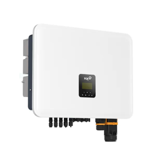
The first is the meter type. The inverter reads the meter’s data via the Modbus protocol, so protocol support must be verified before pairing; the safest option is a meter approved by the manufacturer. For Huawei’s three-phase hybrid inverters, the DTSU666-H meter connects via an RS485 interface, while the DTSU666 meter is the manufacturer’s recommended solution for three-phase FoxEss inverter configurations. Huawei pre-configures the meter’s communication parameters at the factory, which minimizes configuration errors in compatible pairings.
The second factor is the measurement point. The meter’s primary function is power control at the grid connection point; therefore, the accuracy of zero export depends more on the meter’s location than on the hardware itself. We will detail the placement in a separate section.
The third factor is the measurement method and communication. According to the Huawei DTSU666-HW manual, direct connection is required up to 80 A; above this, a current transformer connection is required. Before connecting the smart meter, also plan the route of the signal cable between the meter and the inverter, as there are manufacturer-specified length limits. For example, in FoxESS single-phase systems, the CT cable can be extended up to 30 meters; for distances greater than this, a Modbus meter is required.
The fourth consideration is protection. The Huawei DTSU666-H voltage meter has a built-in fuse for each phase in its terminals, whereas other meters require an external disconnect switch installed near the meter. Always design according to the specific meter’s instructions.
Direct measurement or CT measurement: when to use which solution?
The choice between the two solutions is primarily determined by the expected current. In direct measurement, the phase conductors pass directly through the meter, so there is no transformation ratio and no CT direction that could be misaligned. The limitation is the meter’s rated current: the Huawei DTSU666-HW can be connected directly up to 80 A, and the direct-measurement version of the DTSU666 is also designed for systems up to 80 A. If the connection falls within this range, this is the simplest solution, but the main line must be cut to make the connection.
With CT-based measurement, the meter measures current through current transformers without cutting into the main line; therefore, this is the typical solution for high-current industrial and commercial systems. In this case, the three-phase smart meter can operate with two types of current transformers. One is the milliamperes-output CT supplied by the manufacturer, such as 100 A/40 mA or 250 A/50 mA. The other is a standard current transformer with an amperes secondary output (e.g., 400/1 A), for which the transformation ratio must be set in the meter after wiring.
For the latter, a strict safety rule is that the secondary circuit must never be opened while under load. An open secondary circuit can induce voltages as high as kilovolts; therefore, the IEEE C57.13 standard also prohibits such operation, and the secondary must be short-circuited before disconnection.
In short: direct measurement is the logical choice for low currents, while CT-based measurement is the logical choice for high currents; the specific type is determined by the inverter’s compatibility list.
CT Connection Direction: How Can Incorrect Import–Export Measurements Be Avoided?
The meter determines the direction of power based on the relative phase relationship between voltage and current. If the directions of the two do not match, their product will be negative—meaning that power consumption appears as power injection, and vice versa. According to electrical engineers’ experience, this can be caused by four factors: the CT being installed in the wrong orientation on the conductor, the CT’s secondary wires being swapped at the terminals, the voltage meter wires being swapped, or actual power being fed back into the grid. Furthermore, two errors can cancel each other out, so a value that appears correct is not, in and of itself, conclusive evidence.
The correct CT connection direction varies by manufacturer, so there is no general rule. According to the FoxESS manual, the CT arrow must point toward the grid; however, other manufacturers specify that the arrow should point toward the load. For Huawei meters, the arrow direction must follow the direction indicated on the wiring diagram, and on the secondary side, the polarity of the IA and IA* terminals is equally important.
If a CT has been installed upside down, the error can be corrected by swapping the secondary wires (S1 and S2), but this should only be done with the primary conductor de-energized or the secondary short-circuited, and the modification must be recorded in the documentation. Some inverters detect a reversed CT and correct it via software; however, a physical correction is preferable because it avoids confusion during future servicing. We will demonstrate the polarity check after wiring step by step during the troubleshooting phase.
Phase Sequence and Phase Identification for Three-Phase Smart Meters
A three-phase smart meter measures power per phase; therefore, each current transformer must be connected to the same phase as the one whose voltage is received by the corresponding meter input. The manufacturer’s wiring instructions clearly specify this: the CT connected to the IA/IA* terminals is for L1, the one connected to IB/IB* is for L2, and the one connected to IC/IC* is for L3. For example, if the CT for phase B is connected to the voltage of phase A, the power reading for that phase will be completely incorrect, and so will the total value.
When identifying phases, do not rely on the color of the wires. According to current color codes, L1 is brown, L2 is black, L3 is gray, and the neutral wire is blue; however, in many older buildings, completely different colors are used in accordance with standards from the last century. Measurements are more reliable: approximately 400 V should be measured between two phases, and approximately 230 V between a phase and neutral. So if you measure approximately 400 V between one of the meter’s voltage inputs and the conductor connected to the corresponding CT, the connection is definitely incorrect. Only perform measurements under voltage with the appropriate equipment and protective gear.
Don’t forget the neutral conductor: in a three-phase, four-wire connection, the meter also has a separate N terminal. Some inverters detect incorrect phase assignments and even correct them automatically. The troubleshooting guide for the Huawei meter specifies that, in the event of an incorrect connection, the first step is to check the phase sequence of the voltage and current.
Connecting an inverter meter: where should the measurement point be?
The rule for the measurement point is simple: the inverter meter should measure at the grid connection point, immediately after the billing meter and before any branch circuits. This ensures that everything flowing between the building and the grid passes through the CTs or the meter, whether it’s consumption or feed-in. For accurate control, the meter must measure the net power flow at the point where the facility connects to the grid.
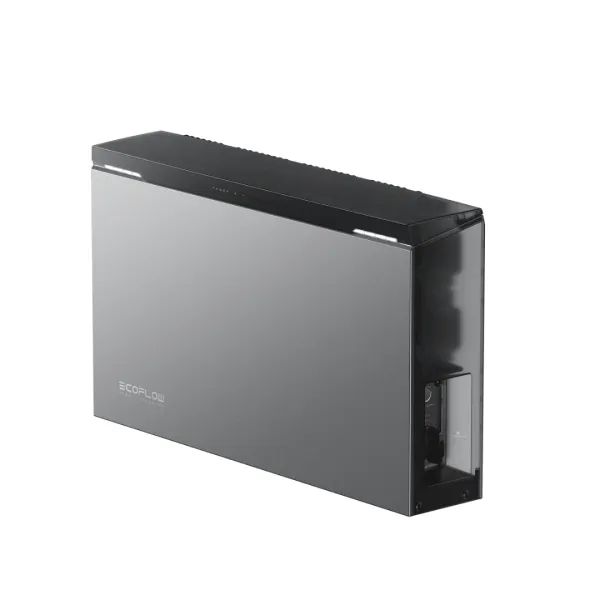
Among the EcoFlow inverters, the wiring diagram for the three-phase PowerOcean illustrates this well. The grid CTs are located after the utility meter and the circuit breaker, and before the uncontrollable loads and the hybrid inverter’s GRID connection. The backup loads are connected to the inverter’s BACKUP output, and according to the manufacturer, the GRID connector must not be connected to the BACKUP terminal.
A common mistake is installing the CT on a branch circuit rather than the main power supply line. The FoxESS manual also explicitly requires that the CT be installed on the incoming phase conductors. In this case, the meter only detects a portion of the household’s electricity usage, and the consumption curve either follows the generation curve or occasionally turns negative.
If a grid-tied solar inverter is already in operation in the home, its AC output should also be routed past the metering point to the side of the house. According to the EcoFlow manual, in this case, the existing system’s generation first supplies the loads and then charges the battery. The details of a multi-inverter setup are discussed in a separate section.
RS485 Connection for Hybrid Inverters
In systems from Huawei, FoxESS, and EcoFlow, the meter communicates with the inverter via an RS485 line, with DTSU666-type meters using the Modbus RTU protocol. This is an interference-resistant solution, but only if the cabling, addressing, and termination are all correct. RS485 connection errors are insidious: even with a single miswired device, the bus often continues to function partially, though data errors become increasingly frequent. The following three points outline the details most commonly overlooked during installation.
A/B Polarity and Wiring Rules
The basic rule: A to A, B to B. The problem is that manufacturers do not label the wires uniformly; some use A/B, others use +/- or D+/D-, and even the meanings of A and B can be reversed. If the meter does not respond even though the parameters are correct, the first thing to do is to swap the two wires. Reversed polarity does not cause damage; it simply interrupts communication.
The cable should be twisted-pair, have a characteristic impedance of 100–120 Ω, and be shielded. The EcoFlow requires a shielded network cable rated at least CAT5, and connects signals A and B to wires 1 and 2 according to the T568B standard—that is, to a twisted-pair. FoxESS also accepts the twisted-pair wires of a CAT5 cable for extending the CT cable. The key is that the A and B signals must always travel in the same pair.
Ground the shield at only one end, because grounding at both ends creates a ground loop, which introduces noise into the signal. Checking the ground connection of the shield is also included in the Huawei SmartLogger’s troubleshooting steps. Route the signal cable away from 230 V power lines, and if crossing is unavoidable, ensure it occurs at a right angle. When using multiple devices, the bus should run in a daisy-chain configuration from device to device, without any star-point branching.
Modbus Addressing and Communication Parameters
Modbus RTU operates on a master–slave principle: the inverter sends a query, and the meter responds at a specified address. If the meter’s address, baud rate, or parity does not match the inverter’s settings, communication will not be established, even if the wiring is correct.
The factory default settings for the Huawei DTSU666-H are: Modbus protocol, 9600 bits/s, address 11, no parity, 1 stop bit. The baud rate can be set between 1,200 and 9,600 bits/s; for the DTSU666-HW version, it can be set between 4,800 and 115,200 bits/s, also with a default value of 9,600 bits/s. Huawei sets the meter’s parameters at the factory and recommends that you check and modify them only in the event of a communication error. The menu is accessible via the meter’s buttons; the factory password is 701. EcoFlow also ships a pre-configured meter and specifically requests that you do not change these settings.
If there are multiple meters on a single bus—for example, under a Huawei SmartLogger—the addresses must not be duplicated. On both the inverter and data logger sides, you must select the meter type and communication port. The baud rate and parity must match on both sides. If the cabling is correct, it is worth checking the inverter menu for the error: incorrect meter type, incorrect port, or different baud rate.
Terminating Resistor and Communication Cable Length
The terminating resistor absorbs signals reflected from the end of the cable. The rule is: a 120 Ω resistor at each of the bus’s two physical ends—and exactly two. A third termination overloads the bus, and the signal level may fall below the standard minimum. Many devices have a switchable, built-in termination. For devices located in the middle of the bus, this must be turned off. You can also check the number of terminations on powered-off devices by measuring resistance; we’ll demonstrate this procedure in the troubleshooting section.
In short, point-to-point connections, at 9600 bits/s, termination may often be omitted for distances under 10 meters. However, the recommended practice is to terminate both ends, because even an unterminated bus can cause errors in noisy environments. The specific solution is always determined by the manufacturer’s specifications.
The theoretical limit for cable length at 9,600 bits/s is approximately 1,200 meters; at higher data rates, it is significantly shorter. In practice, however, the manufacturer’s limit is the guiding factor, and this may be much stricter, as we saw in the design considerations. Branches should be as short as possible: at 9,600 bits/s, they should be less than 1 meter. A maximum of 32 devices can be connected to a single segment using standard transceivers. If the meter must be installed in a meter cabinet farther away from the residential building, check the cable length and route in the manufacturer’s data sheet before installation.
Smart Meter Connection in a Multi-Inverter System
With multiple inverters, the basic principle remains the same: a single meter monitors the grid connection point, and a control device makes the decisions. In this case, a central controller distributes the allowed feed-in among the inverters. When planning the smart meter connection, therefore, first decide which device will be the master.
According to Huawei’s documentation, in a Smart Dongle cascade, the meter and the Smart Dongle are both connected to the same master inverter. With the three-phase MBL0 series, up to three inverters can be cascaded in this network. Larger systems are managed by the SmartLogger, in which case the meter is also connected to the SmartLogger. The two network solutions cannot be mixed within a single system. An important limitation is that Huawei does not support per-phase asymmetric control in a Smart Dongle network consisting of parallel-connected inverters. For more details on this at an industrial scale, see our article titled “Huawei Smart Logger and Smart Guard Solar Meters in Industrial Systems.”
A special case arises when a hybrid inverter is added to an existing grid-tied inverter system. In the FoxESS three-phase H3 Pro system, a second DTSU666 meter is required to measure the existing generation, and its serial number must not match that of the grid meter. With EcoFlow’s three-phase system, however, the configuration and wiring of the existing solar system’s meter can remain unchanged. In both cases, the manufacturer’s cascade and expansion diagrams take precedence over the logic you may be accustomed to from the previous system
Smart Meter and Zero Export: How Does Feed-in Limitation Work?
In zero-export mode, the meter continuously measures import and export power at the grid connection point, and the controller compares this to the set target, which is often 0 W. If feed-in occurs, the inverter reduces the solar panel output or charges the surplus into the battery, and the control loop remeasures and corrects within a second. Fast, accurate measurement is key because slow detection itself can cause unwanted feed-in. Setting a small consumption margin therefore reduces accidental feed-in caused by rapid load changes.
The same logic applies to dynamic limiting, except that the target is not zero but the allowed feed-in value. The inverter’s power meter is therefore not an accessory but the input for the control system: if the measurement is incorrect, the limiting will also be incorrect.
In a three-phase system, it also matters whether the limitation is applied in aggregate or on a per-phase basis. Huawei, for example, supports per-phase control: in this case, the feed-in on any single phase cannot exceed the set threshold, and the inverter adjusts its output to match the load on each phase.
The domestic context: HMKE feed-in, which had been suspended as of November 1, 2022, was reinstated in most of the country as of January 1, 2024. You can check whether feed-in is permitted at a specific location for informational purposes on the MEKH website using the POD identifier. The specific limit value is always determined by the network permit.
Incorrect or negative consumption values: what should you check first?
The inverter does not measure the home’s consumption directly: it calculates it based on its own output and data from the utility meter. An incorrect or negative consumption value therefore primarily indicates a measurement error, and the cause can often be deduced from the symptom.
As a first step, read the meter’s own display and compare it with the inverter’s reading. If the meter shows the correct value but the inverter does not, look for the error in the inverter’s settings, such as the meter type, the selection between the meter and the CT, or the CT parameters.
If you see negative power at night, even without solar generation or battery discharge, this indicates an error in the CT connection direction or phase assignment, since there is nothing to feed into the system at that time. If the value is negative on only one phase but positive on the others, it is highly likely that the CT for that phase is reversed.
If the consumption curve moves in tandem with solar production, the CT is typically in the wrong location, such as at a branch point. If consumption is unrealistically high and increases along with production, the grid and load values may have been swapped, which indicates a reversed CT or an incorrect meter direction setting.
If the inverter’s data consistently and proportionally differs from the utility’s meter reading—for example, by approximately 20%—this is more likely a transmission error, which we discuss in the CT transmission section.
Since two errors can cancel each other out, always double-check all three phases after making a repair.
Communication errors between the smart meter and the inverter
If the connection between the meter and the inverter is lost, the inverter will trigger an alarm. For Huawei SUN2000 inverters, for example, this is alarm code 2067, “Faulty power collector.” Without meter data, the control system operates blindly, and depending on the connection requirements, the inverter will either set its output to a predetermined level, shut down, or simply trigger an alarm. A communication error is therefore not a convenience issue but an operational problem.
Huawei provides four checkpoints for this alarm, which can also be used as a general sequence. Does the meter type set in the inverter match the one actually installed? Do the communication parameters match? Is the meter receiving power? Is the RS485 connection error-free? Huawei also emphasizes that you should maintain the meters’ factory data rate, because changing it may cause the meter to go offline, trigger an alarm, or affect the inverter’s output power.
If the connection is only intermittently lost, this typically indicates interference or a cabling error: a star-point branch, a missing or unnecessary termination, ungrounded shielding, or a shared route with a high-current cable. With a star topology, continuous CRC errors and timeouts may occur at higher data rates. On a multi-device bus, even a single device with different settings is enough to cause an error: according to the Huawei SmartLogger documentation, all devices on a chain must have the same data rate, protocol, and parity, and no more than 30 devices should be connected to a single branch.
Pay special attention if an external power management device or data logger is also connected to the meter bus. On an RS485 bus, only one master can send a query at a time; a collision between two querying devices will cause a communication error.
CT ratio and measurement accuracy: common configuration errors
Transformer ratio errors are insidious because the direction is correct and the shape of the curves appears normal—only the values are proportionally distorted. If the transformation ratio set on the meter does not match the CT actually installed, both power and energy readings will be incorrect, even with a physically correct connection. The value to be set is the ratio of the nominal primary current to the nominal secondary current: 40 for a 200/5 A CT, and 20 for a 100/5 A CT.
For dedicated CTs with milliampere outputs, no conversion is necessary; in this case, the compatibility between the CT and the meter is critical. For example, in a case documented on the FoxESS community forum, a 100 A/40 mA CT was installed in place of the factory-installed 100 A/33.33 mA CT, and the inverter displayed values that were approximately 20% higher.
An oversized CT also compromises accuracy because, at low loads, it operates at a fraction of its rated current. The Huawei DTSU666-H has accuracy class 1: the error limit is ±1.5% between 1% and 5% of the rated current, and ±1% above that. Huawei does not even recommend the DTSU666-HW for low-power systems or connection points requiring high control accuracy, because with a 400/1 CT, the error can be ±2 A. According to professional recommendations, the normal operating current should be approximately 60–80% of the CT’s rated primary current.
Two additional pitfalls: in a three-phase, three-wire network, Huawei states that the connection mode must also be set; otherwise, the displayed voltage will be incorrect. Furthermore, if a second meter is connected to the same CT at a later date, the CT’s load capacity may be insufficient.
Step-by-Step Troubleshooting
After connecting the smart meter, it is always best to perform troubleshooting in the same order: first check the measured baseline values, then the direction, and finally the communication and settings. This ensures that an earlier error does not skew the results of subsequent steps. The following three steps provide a measurement protocol for the symptoms described in previous sections, allowing measurements to either confirm or rule out a suspected issue. Measurements should only be performed by a qualified professional using appropriate equipment and protective gear, in accordance with the manufacturer’s instructions.
Checking Phase Voltages and Current Values
Start by checking the meter’s display: three-phase meters show the voltage, current, and active power for each phase. The expected values are approximately 230 V between a phase and neutral, and approximately 400 V between two phases. If a phase is missing or significantly different, first check the connection and protection of the voltage measurement leads.
Then compare the values using independent measurements: measure the voltage with a multimeter and the phase currents with a clamp meter. A deviation of one or two percent is natural, because no two instruments measure exactly the same way, and while some meters measure true RMS, simpler multimeters do not. If you suspect the meter itself, there is a simple consistency test: after disconnecting the power, connect all three voltage inputs and all three CTs to the same phase; the values for the three phases should be nearly identical.
Correct voltage and current readings do not necessarily mean correct power. In the case of incorrect phase assignment or reversed CTs, the voltage and current readings may be accurate, but the power and power factor will be incorrect. With a purely resistive load, such as an electric water heater or a radiant heater, the power factor should be close to 1; a value around −1 indicates reversed polarity. If the power per phase and the power factor are both correct, you can proceed to check the direction.
Checking Import and Export Directions
Test the direction using a known load. Turn off the inverter’s output, make sure the battery isn’t discharging, and then turn on a known load. At this point, the meter should show power consumption, and the power consumption counter should increase. If, instead, the feed-in counter increases, this indicates reverse direction. The polarity of the power draw varies by manufacturer: in some cases, with a correct connection and the inverter turned off, the grid power is negative; in others, it is positive. Therefore, always check the manufacturer’s polarity convention in the manual.
For three-phase systems, check each phase individually. When a single-phase load connected to a known phase is turned on, only the value for that specific phase should increase, with the correct sign. If the value increases on another phase, the phases are reversed; if it increases with the wrong sign, the CT is reversed. Repeat this for all three phases.
Next, check the generation side. For solar power generation and low consumption, if the grid permit allows feed-in, the meter should show export. In zero-export mode, the grid power should remain at the set target, typically around 0 W. Some inverters also feature a meter and CT self-test that can be run at the end of installation, which indicates incorrect polarity or phase assignment. This provides quick confirmation but does not replace the manual test described above.
Checking RS485 Communication and Inverter-Side Settings
If the meter is not communicating, check the meter first. The display on many meters flashes when RS485 data traffic is occurring. If there is no traffic, the fault lies in the line or in the inverter’s response.
You can check the line with two simple measurements. With devices turned off, the resistance measured between A and B with two 120 Ω terminations is approximately 60 Ω. A value significantly different from this indicates missing, faulty, or excessive terminations; a value close to 0 Ω indicates a short circuit. On a powered bus with no data traffic, the DC voltage between A and B is typically 0.2–0.5 V; a value close to 0 V indicates a lack of bias voltage or a dead line. Also pay attention to the connectors: RS485 does not have a standardized RJ45 pinout, so a standard patch cable plugged between devices from two different manufacturers could even connect the data line to a power contact.
On the inverter side, verify that the meter is enabled and that the selected meter type and port match the installed configuration. The address, data rate, and parity must match those of the meter, and the feed-in limitation parameters must comply with the grid permit. Finally, check in the manufacturer’s app to see if the meter is online and whether the inverter is seeing the same grid power as shown on the meter’s display.
SOLARKIT Commissioning Checklist After Connecting the Smart Meter
The list below summarizes the steps in this article as a pre-handover checklist. Check off each item and record the results in the commissioning report.
-
Meter type: The meter is listed on the inverter manufacturer’s compatibility list, and its communication parameters are set to factory defaults.
-
Measurement point: The meter or CTs are installed on the incoming phase conductors, downstream of the utility meter and before any branch circuits.
-
CT direction and phase: The arrow is oriented as shown in the manufacturer’s diagram, and each CT is connected to the phase of its corresponding voltage input.
-
Neutral conductor and protection: The N conductor is connected; the protection of the voltage measurement branches complies with the meter’s specifications.
-
Reference values: The phase voltages and currents match those measured with a multimeter and alligator clips; with an ohmic load, the power factor is around 1.
-
Polarity test: With the inverter turned off and the battery fully charged, the meter displays a reading for each phase, in accordance with the manufacturer’s specified polarity.
-
CT ratio: The ratio set on the meter matches the value listed on the nameplate of the installed CT.
-
RS485: The A–B polarity is correct, the shielding is grounded at one end, and you have verified the number of short circuits by measuring resistance.
-
Inverter settings: The meter is enabled; the type, port, and limit value are set according to the network authorization; the meter is online.
-
Documentation: Take photos of the CTs’ arrow directions and the terminals, and save a screenshot of the live values in the app. A single photo of the arrow direction can save you the trouble of a second, unnecessary service call.
Frequently Asked Questions
Can I install the smart meter myself?
No, it is not recommended. The manufacturer’s installation instructions specify that this work should be performed exclusively by a qualified electrician familiar with local standards and wearing appropriate protective gear. The work takes place near live power lines, and the secondary circuit of conventional current transformers can produce life-threatening voltages if interrupted while under load. Furthermore, an incorrect connection can disrupt the control system, which may lead to unintended power injection or unnecessary power consumption.
Is a smart meter required for a hybrid inverter if there is no feed-in limit?
Yes, to optimize self-consumption. Without a meter, the inverter cannot monitor grid import and export; as a result, with some manufacturers, the battery only charges and discharges according to scheduled settings, and the operating mode that automatically minimizes power draw is not available. Meter data is also required to display the home’s energy consumption, and “zero export” and dynamic limiting simply won’t work without a meter.
Which way should the CT arrow point?
There is no general rule; it varies by manufacturer. According to the FoxESS manual, it should point toward the grid; other manufacturers specify that it should point toward the load; and for Huawei meters, it should point in the direction indicated on the wiring diagram. After installation, with a known load and the inverter turned off, check to see if the meter shows power consumption. If the CT is installed backwards, this can be corrected by swapping the secondary wires, but only when the primary wire is de-energized or the secondary is short-circuited.
Why does my inverter show negative power consumption?
The inverter calculates consumption based on its own output and data from the utility meter; therefore, a negative value indicates a measurement error. Typical causes include a reversed CT, incorrect phase assignment, or a CT installed on a branch circuit. If you see a negative value at night, even without generation or discharge, it is almost certainly an installation error.
Can I use a meter from another manufacturer with my hybrid inverter?
Only if the inverter manufacturer explicitly supports it. The inverter reads the meter’s data via a specific protocol, so manufacturers specify the supported meter types. EcoFlow, for example, notes that meter compatibility may vary by region and version. Huawei’s three-phase MBL0 series also supports only specific meter types, including the DTSU666-H 250 A/50 mA. Therefore, always check the manufacturer’s compatibility list before making a purchase.