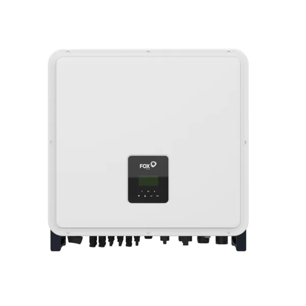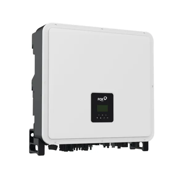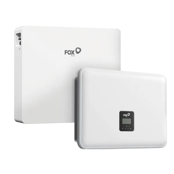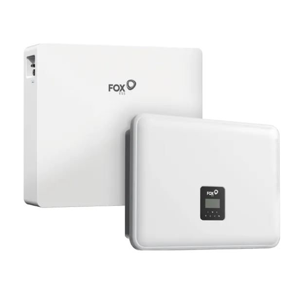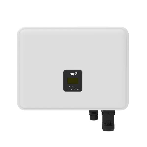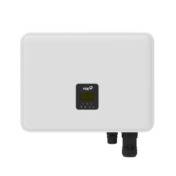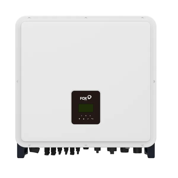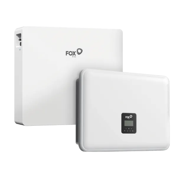
FoxESS Battery and Inverter Compatibility
Matching a FoxESS battery with an inverter isn’t a task you can just check off a catalog. The number of modules, the voltage range, and the communication settings all determine whether the system can be commissioned. If this becomes apparent on-site, it’s already too late: an incorrect match means a failed commissioning, a return shipment, and a dissatisfied customer. That’s why we’ll start by outlining what you should check before approving a complex system design.
Next, we’ll go over the technical differences between FoxESS energy storage units: the number of modules in the EP6 and its parallel expansion capabilities, the capacity and voltage specifications of the EP12, and the role of the CQ7 in higher-capacity systems. A separate section discusses which inverter families are compatible with these batteries.
The second half focuses on practical application: the purpose of the master and slave modules, how to set up BMS and CAN communication, and what decisions need to be made regarding cabling, fuses, and future capacity expansion. The concluding set of questions addresses the most common design issues regarding FoxESS battery compatibility. Each statement is backed by a manufacturer’s data sheet or installation documentation; references are provided for each section.
What should be checked before designing a complex FoxESS system?
The issue of compatibility rarely comes down to whether a given battery works with the inverter. Much more often, it’s about how many modules it works with, the minimum number required, and any functional limitations. There are five key points to confirm before finalizing your system design.
Inverter family and generation. The model name alone isn’t enough. Hybrid and AC-coupled versions (H1/AC1, H3/AC3) fall under separate configuration tables, and the generation also matters: the first-generation H1 allows for a lower maximum battery voltage than the second.
Minimum and maximum number of modules. This is the most common design error. The manufacturer’s configuration guide specifies both a minimum and maximum number of modules for every inverter-battery pairing. The HV2600 module requires at least three when paired with an H3 inverter, but only two are needed with an H1. Anyone who looks only at the upper limit will end up selling an under-designed system.
Country-specific variations. The configuration table is not standardized across all markets. In Italy, stricter minimum requirements apply due to CEI 0-21 certification, so a setup that works in another country cannot be applied automatically.
Warranty risk. The manufacturer explicitly states that if the system is built outside the configuration guidelines, it reserves the right to reject warranty claims. This is why verifying FoxESS battery compatibility is also a matter of business risk management, not merely a technical formality.
Functional limitations. Certain configurations lack specific functions. With an H3 inverter and either three HV modules or a 1CM+2CS configuration, black start is not supported—meaning the system cannot be started without PV or the grid, relying solely on the battery. It is better to inform the customer of this in advance rather than during the first power outage.
Therefore, the first step in planning is not capacity calculation, but downloading the latest version of the manufacturer’s configuration table.
Technical Differences Between FoxESS Energy Storage Systems
The FoxESS product line features two energy storage architectures that differ in their underlying logic, and this difference determines how the system can be expanded later. This choice must be made at the very beginning of the system design, as changing it later would require replacing the cabinet.
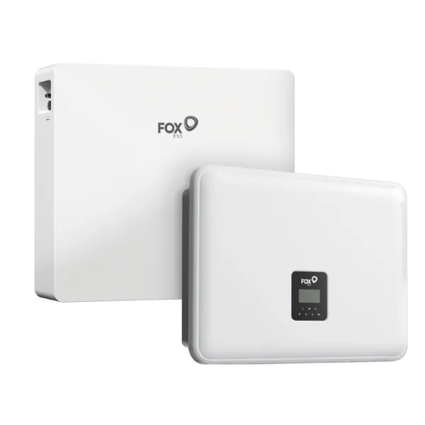
The EP series consists of standalone battery units that can be mounted on a wall or placed on the floor. Expansion is achieved through parallel connection, up to a maximum of four units; starting with the second unit, an HV junction box is required.
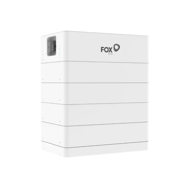
The CQ series, on the other hand, consists of floor-standing modules stacked in series: a master module handles system control, while the slave modules provide the storage capacity.
Thus, the FoxESS energy storage systems differ not only in capacity but also in their expansion methods. In the following three sections, we will review the design parameters of the EP6, EP12, and CQ7.
FoxESS EP6-Compatible Inverters, Number of Modules, and Parallel Expansion
According to the EP6 Plus datasheet, the battery is compatible with all series of the H1, H3, H3 Smart, and H3 Pro inverter families. It does not work with third-party inverters because it is a closed-loop system that uses high voltage and CAN communication.
For planning purposes, the rated capacity of 5.76 kWh alone is insufficient. The nominal voltage is 192 V, the operating range is between 174 and 219 V, the maximum charge and discharge current is 30 A, but the recommended charge current is only 15 A. If the customer expects fast charging, this figure should be shown to them, not the peak value.
For parallel expansion, the data sheet allows for a maximum of four units, or 23.04 kWh, and an HV junction box is required starting with the second module. However, the manufacturer’s sizing guide allows for up to eight modules with the H3 Pro inverter. So, when configuring FoxESS H3 battery systems, the Pro version is the exception to the rule; therefore, for every project, take this number directly from the current sizing table—don’t rely on memory.
For outdoor installation, two factors are important: IP65 protection and operating temperature. It operates between 0 and 55 degrees Celsius during charging and between -10 and 55 degrees Celsius during discharging. The heating function is listed as an optional item on the data sheet; it is not standard equipment. In cold-climate installation locations, this is a specific ordering decision, not a minor detail.
The 51 kg unit, measuring 380 x 640 x 185 mm, can be installed either on the wall or on the floor; however, if mounting it on the wall, check the structural load-bearing capacity beforehand.
FoxESS EP12 System Design: Capacity, Voltage Range, and Inverter Connection
The EP12 has a rated capacity of 11.52 kWh, a rated voltage of 384 V, and an operating range between 348 and 438 V. This is the most significant difference compared to the EP6: they do not share the same voltage platform.
The practical implication: the two model types cannot be mixed within a single system. The manufacturer’s documentation allows mixing within the same voltage class—for example, EP11 and EP12 in a single system—provided that the same latest firmware is available for and installed on all modules. There is no authorization to pair 192-volt and 384-volt units.
Something many people overlook when sizing a system: the EP12 has twice the capacity of the EP6, but the maximum charge and discharge current for both is 30 A, and the recommended charge current is 15 A. In other words, double the capacity does not mean double the power. If the customer’s goal is high peak load, they should choose an inverter rather than focusing on capacity.
On the inverter side, the FoxESS EP12 works with the H1, H3, and H3 Pro families via CAN communication. When designing the system, verify that the inverter’s battery-side voltage range covers the upper limit of 438 volts. According to the manufacturer’s forum, for example, the first-generation H1 does not support the EP12’s heating system, whereas the second-generation model does. This is a detail that becomes apparent during commissioning.
For system expansion, four units can be connected in parallel, providing a system capacity of 46.08 kWh, using an HV junction box. However, the physical dimensions pose a significant logistical challenge: each module weighs 98 kg and measures 710 x 640 x 185 mm. This must be taken into account during both lifting and mounting.
Using the FoxESS CQ7 Battery in Higher-Capacity Energy Storage Systems
The CQ7 is built on a different architecture than the EP series. Here, the modules are connected in series; one CQ7-M master and up to thirteen CQ7-S slave modules form a stack. Each module has a capacity of 7.02 kWh, and the maximum system capacity is 98.28 kWh.
The serial configuration has one consequence that cannot be ignored during design: the system’s nominal voltage varies with the number of modules. With two modules, it is 115.2 V; with fourteen, it is 806.4 V; and the operating range extends from 104.4 to 919.8 V. In other words, the number of modules is not determined by the desired capacity, but rather the minimum is dictated by the inverter’s battery-side voltage window.
It’s in a different league in terms of power as well. The recommended charging and discharging current is 50 A, the maximum is 80 A, and the peak discharge is 110 A for one minute. This is sufficient to handle higher consumer peaks and three-phase systems, in contrast to the EP series’ 30-amp limit.
However, the installation site must be assessed. The width and depth of the tower are fixed at 660 x 360 mm, but its height increases with the number of modules: 420 mm for two modules and 2,280 mm for fourteen modules. The weight scales accordingly, ranging from 105.5 kg to 711.5 kg. Floor load capacity, interior height, and delivery route: all three are design parameters.
In cold environments, the FoxESS CQ7’s optional heating function extends the operating range: without it, charging begins at 0 degrees Celsius, but with the heating function, it operates down to -25 degrees Celsius. For outdoor, rack-mounted installations, this is a standard order item—not a software feature that can be activated retroactively. We have removed this decision from our agenda: all FoxESS energy storage systems in our product lineup are available exclusively in heated versions, so charging in cold weather is not a separate ordering option.
Which inverter families are compatible with FoxESS batteries?
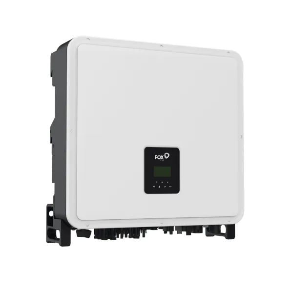
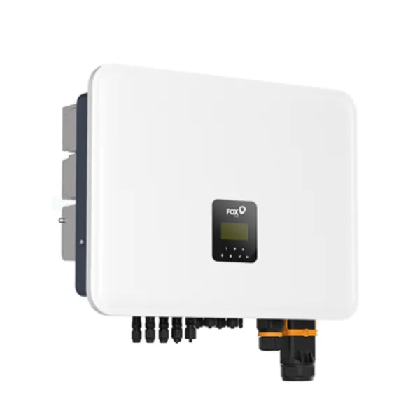
The FoxESS battery forms a system with our own high-voltage inverter family. This has the advantage that the battery, inverter, and communication components all come from the same manufacturer, are designed to work together, and have been tested as a unified system. Consequently, when designing a system, it’s best to stick with the FoxESS product family, as low-voltage batteries with different architectures do not fit into this configuration.
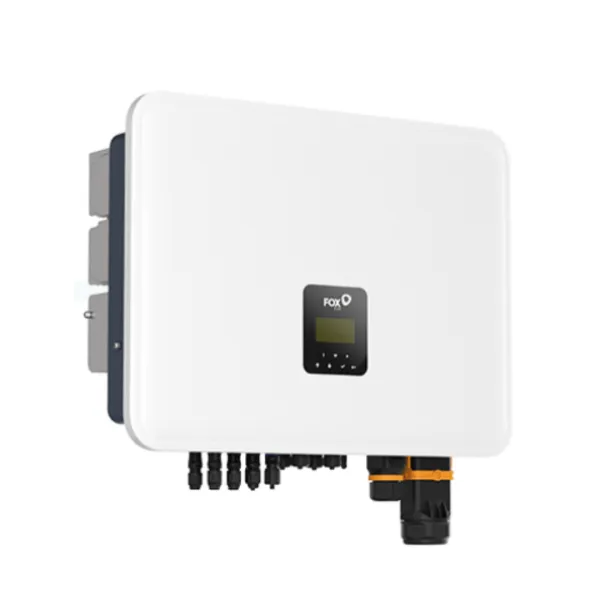
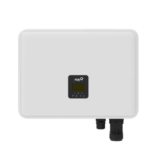
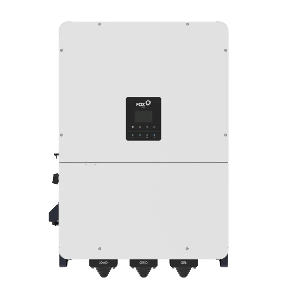
There’s still plenty of choice, though. Single-phase hybrid and AC-connected units: H1 and AC1. Three-phase units: H3/AC3, H3 Smart, H3 Pro, and H3 Plus. In addition, there are the pre-assembled, all-in-one AIO and PowerQ systems. You can view the full range of FoxESS inverters on our category page.
The practical question isn’t which series to choose, but how many modules each series can handle. Here, the H3 Pro offers the greatest flexibility: while the H1 and H3 series support four EP modules, the Pro version supports eight. If you’re assembling a system with higher capacity using FoxESS EP6 modules, this difference means a single inverter can handle the task.
For battery towers expanded in series, a simple rule applies: one inverter handles one tower, and if you connect two towers, build them with the same number of modules—and thus the same voltage. The solution for this is the inverter’s parallel port or an H3 Pro-level unit.
For FoxESS H3 battery configurations, it’s therefore a good idea to compare three pieces of data before placing an order: the inverter type and generation, the minimum and maximum number of modules in the battery family, and the inverter’s battery-side voltage window. If these three figures match, commissioning will go smoothly, and the customer will get exactly what you promised them from day one.
The Roles of Master and Slave Battery Modules in FoxESS Energy Storage Systems
In FoxESS battery towers, master and slave modules differ not in size but in function. The master is the system controller: it contains the BMU, the switching element, and the CAN communication interface, through which the tower communicates with the inverter. The slave modules provide pure capacity.
This determines the ordering logic. Each tower requires exactly one master module and at least one slave module; thus, the smallest operational system consists of two modules, with a capacity of 14.04 kWh. If you build multiple towers, each one will have its own master module.
The minimum number of modules is determined by the inverter, and the specified quantity always includes the master. For single-phase H1-G2 and AC1-G2 systems, the range is two to seven modules—that is, one master and one to six slaves. For the H3 Smart, the range is three to twelve, meaning one master and two to eleven slaves. For the H3 Pro, the range is four to twelve per tower with two towers; for the H3 Plus, the range is four to fourteen with up to three towers, and each tower has its own master. This table is your best friend when preparing a quote.
This architecture also makes future expansion convenient. If the customer wants to add capacity, they simply need to order slave modules; the existing master will continue to handle control. The FoxESS battery system is therefore not a closed package, but grows alongside the customer’s needs for years to come.
There’s one thing worth considering during the initial planning phase: the tower’s maximum capacity. If the customer plans to increase capacity within a two-year timeframe, it’s best to select an inverter that accommodates this from the start, because then future expansion will simply involve adding a few modules rather than a complete system overhaul. This discussion is the most worthwhile five minutes of the quoting process.
Proper Configuration of BMS and CAN Communication in FoxESS Battery Systems
Communication is the area where most commissioning time is spent, yet it can be made predictable by following a few simple rules. The communication cable runs from the inverter’s BMS port to the battery’s PCS port. These two terms are not interchangeable, and the quick installation guide also begins with this pairing. For the EP and CQ families, communication takes place via the CAN protocol, as specified in the data sheets.
The second rule concerns termination. For a single EP battery, the two terminating resistive plugs must be inserted into the “link in” and “link out” ports on the left side of the module. For multiple modules, the chain must be terminated in the same way at both ends. If there is no communication during commissioning, this is the first place to check.
The third rule is firmware synchronization. The firmware versions of the inverter and the battery must be compatible with each other, and all modules within a single array should run the same, latest available version. Versions can be checked on the inverter’s user interface, and updates can be requested via installer access or by contacting the manufacturer’s service department.
Completing the commissioning process involves a brief check. After powering on, the BMS indicator lights will first flash rapidly while the system runs the synchronization process, then switch to a steady rhythm without any error indicators. Next, it’s a good idea to start a controlled charge and check whether the inverter is correctly reading the battery’s voltage and state of charge.
Finally, check the monitoring program interface to see if the BMS data is displayed. If the FoxESS battery’s state of charge and temperature are visible there, the communication chain is working properly, and you can monitor the system remotely. These few minutes spent checking beforehand will save you a lot of on-site visits later on, and the customer will also see that everything is based on measured data at the time of handover.
Cabling, Safety, and Future Capacity Expansion for FoxESS Batteries
Planning the cabling is simple if you sketch out the on-site layout in advance. The DC and data cables supplied with the modules are three meters long, but the section between the junction box and the inverter must be kept short—roughly six hundred millimeters. This determines the on-site sequence: the batteries connect to the junction box, and the junction box connects to the inverter’s battery port.
The installation site must meet two requirements. One is orientation: the module may be mounted on a wall or placed on the floor, but it must not be tilted or laid flat. The other is the environment: the area must be free of heat-generating and flammable materials, with sufficient space for heat dissipation.
To power on the system, set the DC switch on each battery to the ON position, then press and hold the power button on the master module for approximately three seconds. For black start, press and hold the button for one to three seconds. Exactly what can be operated in this scenario is described in a separate article: Setting Up a Backup System with the FoxESS System. Note that no communication cable is connected to the PCS port of the slave modules; it’s advisable to check this, along with the terminating resistors, before handover.
Future expansion is most cost-effective if you plan for it during the initial installation. A single module can still be connected directly to the inverter, but a junction box is required starting with the second module. If the customer plans to expand, it’s worth installing the junction box during the first phase, because then adding a second FoxESS battery will only require a few connections—not rewiring.
Keep one thing in mind when expanding: according to the manufacturer’s instructions, different models cannot be mixed in a single system, so any expansion must always use the same model. For this reason, it’s worth sizing the initial energy storage system to meet expected demand. The modular design of FoxESS systems supports exactly this: the initial configuration can be expanded years later if the original plan was well thought out.
Frequently Asked Questions
Does the FoxESS battery work with inverters from other manufacturers?
No, the system is based on its own high-voltage architecture with CAN communication. The battery forms a functional unit with the FoxESS hybrid and AC-coupled inverter families: H1, AC1, H3, AC3, H3 Smart, H3 Pro, and H3 Plus. Low-voltage batteries from third-party manufacturers operate on a different architecture and therefore are not compatible with this system. The advantage is that the manufacturer tests and documents these combinations together.
Can the FoxESS EP6 and FoxESS EP12 be mixed in the same system?
No. According to the installation guide, different models cannot be mixed; furthermore, the two types have different voltage platforms: the EP6 has a nominal voltage of 192 V, while the EP12 has a nominal voltage of 384 V. Therefore, when expanding the system, it is always best to order additional modules of the same model.
How many modules can one inverter handle?
This varies by inverter, so always refer to the current sizing chart. Among EP modules, the H1, H3, and KH series handle four each, while the H3 Pro handles eight. For CQ7 towers, single-phase H1-G2, AC1-G2, and KH systems support two to seven modules per tower; the H3 Smart supports three to twelve; and the H3 Plus supports up to fourteen per tower. The H3 Pro and H3 Plus can manage multiple towers, each with its own master module, allowing even higher-capacity FoxESS battery systems to be built around a single inverter.
Is a junction box required for a single battery?
A single module can be connected directly to the inverter without a junction box. However, a junction box is required starting with the second module, so if expansion is expected, it’s worth installing one during the initial setup. With a single EP module, both terminating resistors must be inserted into the “link in” and “link out” ports. When installing a FoxESS battery system, these small details determine whether the system communicates properly on the first try.
What is the smallest operational CQ7 system?
One master and one slave module, for a total of 14.04 kWh. The master handles control and communication; it does not operate on its own. Each tower requires its own master, and capacity can be expanded with slave modules up to 98.28 kWh. Therefore, when expanding the system, there is no need to order a new master—simply add the slave modules to the existing tower.